目标
设计一个基于FPGA的VGA控制器,可以显示640*480的图片,为下一步学习摄像头做准备。
硬件平台:Basys 3 开发板
原理
标准15针VGA接口共有五个信号接口,如下表所示,其中hsync、vsync为行同步和场同步信号,RGB为模拟信号。
| 信号名称 | 作用 |
|---|---|
| hsync | 行同步信号 |
| vsync | 场同步信号 |
| R | 红色信号 |
| G | 绿色信号 |
| B | 蓝色信号 |

行扫描时序

场扫描时序

VGA时序图
设计
整个电路分为这几个部分:
- VGA控制器
- 图像控制器
- ROM存储
首先是VGA控制器部分,这部分产生行同步信号和场同步信号;
1
2
3
4
5
6
7
8
9
10
11
12
13
14
15
16
17
18
19
20
21
22
23
24
25
26
27
28
29
30
31
32
33
34
35
36
37
38
39
40
41
42
43
44
45
46
47
48
49
50
51
52
53
54
55
56
57
58
59
60
61
62
63
64
65
66
67
68
69
70
71
72
73
74
75
76
77
78
79
80
81
82
83
84
85
86
87
88
89
90
91
92
93
94
95
96
97
98
99
100
101
102
103
104
105
106
107
108
109
110
111
112
113
114
115
116
117
118
119
120
121
122
123
124
125
126
127
128
129
130
131
132
module vga_sync(
input wire clk,reset,
output wire hsync,vsync,video_on,p_tick,
output wire [9:0] pixel_x,pixel_y,
output wire [18:0] addr
);
//定义常数
//VGA 640 * 480 同步参数
localparam HD = 640; //水平显示区域
localparam HF = 48; //水平扫描左边界
localparam HB = 16; //水平扫描右边界
localparam HR = 96; //水平折回区
localparam VD = 480; //垂直显示区域
localparam VF = 10; //垂直扫描顶部边界
localparam VB = 33; //垂直扫描底部边界
localparam VR = 2; //垂直折回区
//模4计数器
reg [1:0] mod4_reg;
reg [1:0] mod4_next;
//同步计数器
reg [9:0] h_count_reg,h_count_next;
reg [9:0] v_count_reg,v_count_next;
//输出缓冲器
reg v_sync_reg,h_sync_reg;
wire v_sync_next,h_sync_next;
//状态信号
wire h_end,v_end,pixel_tick,addr_end;
//地址输出缓冲器
reg [18:0] addr_reg;
reg [18:0] addr_next;
always @(posedge clk or posedge reset) begin
if (reset) begin
// reset
mod4_reg <= 1'b0;
v_count_reg <= 0;
h_count_reg <= 0;
v_sync_reg <= 1'b0;
h_sync_reg <= 1'b0;
addr_reg <= 0;
end
else begin
mod4_reg <= mod4_next;
v_count_reg <= v_count_next;
h_count_reg <= h_count_next;
v_sync_reg <= v_sync_next;
h_sync_reg <= h_sync_next;
addr_reg <= addr_next;
end
end
//模4计数器产生25MHz时钟使能信号
always @(*) begin
if (reset) begin
// reset
mod4_next <= 2'b0;
end
else begin
mod4_next <= mod4_reg + 1;
end
end
// assign mod4_next = mod4_reg + 1;
assign pixel_tick = (mod4_reg == 2'b11)&&(!clk);
//状态信号
//水平扫描结束信号(799)
assign h_end = (h_count_reg==(HD+HF+HB+HR-1));
//垂直扫描计数器结束信号
assign v_end = (v_count_reg==(VD+VF+VB+VR-1));
//地址结束信号
assign addr_end = (addr_reg==(HD*VD-1));
//水平同步扫描模800计数器下一状态
always @(*) begin
if (pixel_tick) begin
if (h_end) begin
h_count_next = 0;
end else begin
h_count_next = h_count_reg + 1;
end
end else begin
h_count_next = h_count_reg;
end
end
//垂直同步扫描模525计数器新下一状态
always @(*) begin
if (pixel_tick && h_end) begin
if (v_end) begin
v_count_next = 0;
end else begin
v_count_next = v_count_reg + 1;
end
end else begin
v_count_next = v_count_reg;
end
end
//地址下一个状态
always @(*) begin
if (pixel_tick) begin
if (addr_end) begin
addr_next = 0;
end else if(video_on) begin
addr_next = addr_reg + 1;
end else begin
addr_next = addr_reg;
end
end else begin
addr_next = addr_reg;
end
end
//同步缓冲器
//h_sync_next 信号在计数器数值为656和751时赋值
assign h_sync_next = (h_count_reg >= (HD+HB)&&h_count_reg <= (HD+HB+HR-1));
//v_sync_next 信号在计数器数值为490和491时赋值
assign v_sync_next = (v_count_reg >= (VD+VB)&&v_count_reg <= (VD+VB+VR-1));
//产生video_on 信号
assign video_on = (h_count_reg < HD) && (v_count_reg < VD);
//输出
assign hsync = h_sync_reg;
assign vsync = v_sync_reg;
assign pixel_x = h_count_reg;
assign pixel_y = v_count_reg;
assign p_tick = pixel_tick;
assign addr = addr_reg;
endmodule
然后是图像控制部分;
1
2
3
4
5
6
7
8
9
10
11
12
13
14
15
16
17
18
19
20
21
22
23
24
25
26
27
28
29
30
31
32
33
34
35
36
37
38
39
40
41
42
43
44
45
46
47
48
49
50
51
52
53
54
module vga_display
(
input clk,reset,
input p_tick,
input [9:0] pixel_x,pixel_y,
input video_on,
input [11:0] rgb_in,
output [14:0] addr_out,
output [11:0] rgb_out
);
parameter DH = 150, DV = 150;
reg [14:0] addr_reg,addr_next;
reg [11:0] rgb_reg,rgb_next;
assign pic_en = ((pixel_x >= 0 && pixel_x < DH) && (pixel_y >= 0 && pixel_y < DV));
always @(posedge clk or posedge reset) begin
if (reset) begin
// reset
addr_reg <= 15'b0;
rgb_reg <= 12'b0;
end else begin
addr_reg <= addr_next;
rgb_reg <= rgb_next;
end
end
always @(*) begin
if (p_tick) begin
if (addr_reg == DH * DV - 1) begin
addr_next = 0;
end else if (pic_en) begin
addr_next = addr_reg + 1;
end else begin
addr_next = addr_reg;
end
end else begin
addr_next = addr_reg;
end
end
always @(*) begin
if (pic_en) begin
rgb_next = rgb_in;
end else begin
rgb_next = 12'b0000_1111_1111;
end
end
assign addr_out = addr_reg;
assign rgb_out = (video_on)?rgb_reg:12'b0;
endmodule
最后ROM储存。
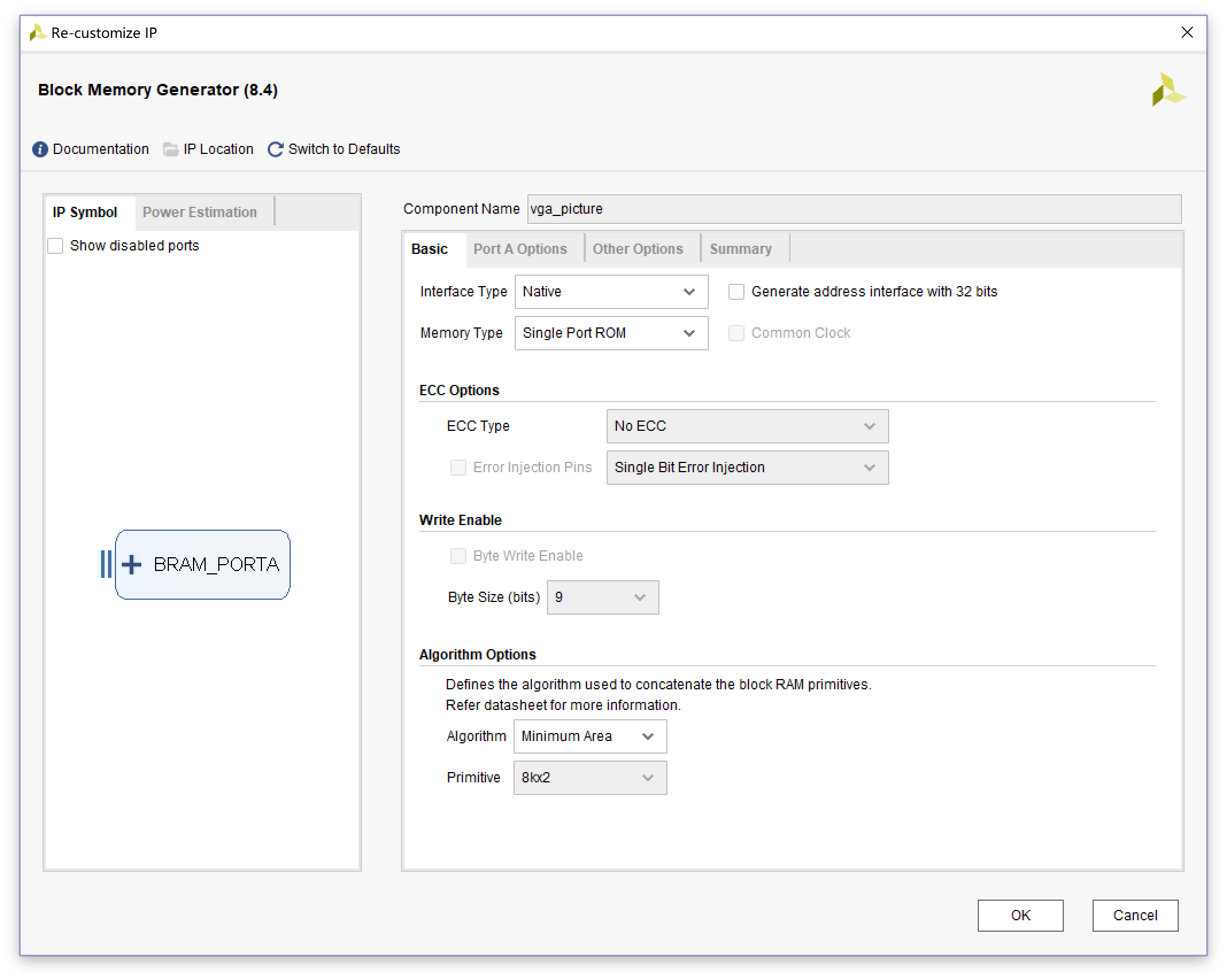
这部分调用了Xilinx官方的IP,在IP Catalog 中选择Block Memory Generator,
首先在Basis里选择Memory Type为Single Port ROM;
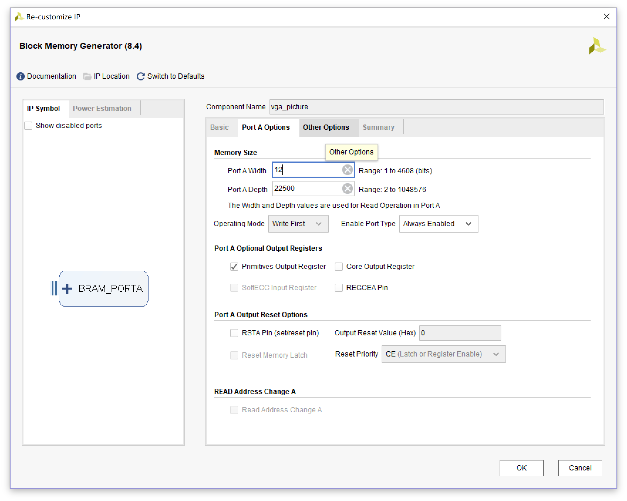
然后在Port A Options 里设置数据宽度和深度,因为Basys3上的VGA是RGB444格式的,所以数据宽度设为12位,深度可以理解为像素数,本来是想显示640*480的图片的,但Basys3上的RAM容量不够,所以就显示的150*150的图片,则深度为22500(150*150),不需要使能,所以Enable Port Type设为Always Enable;
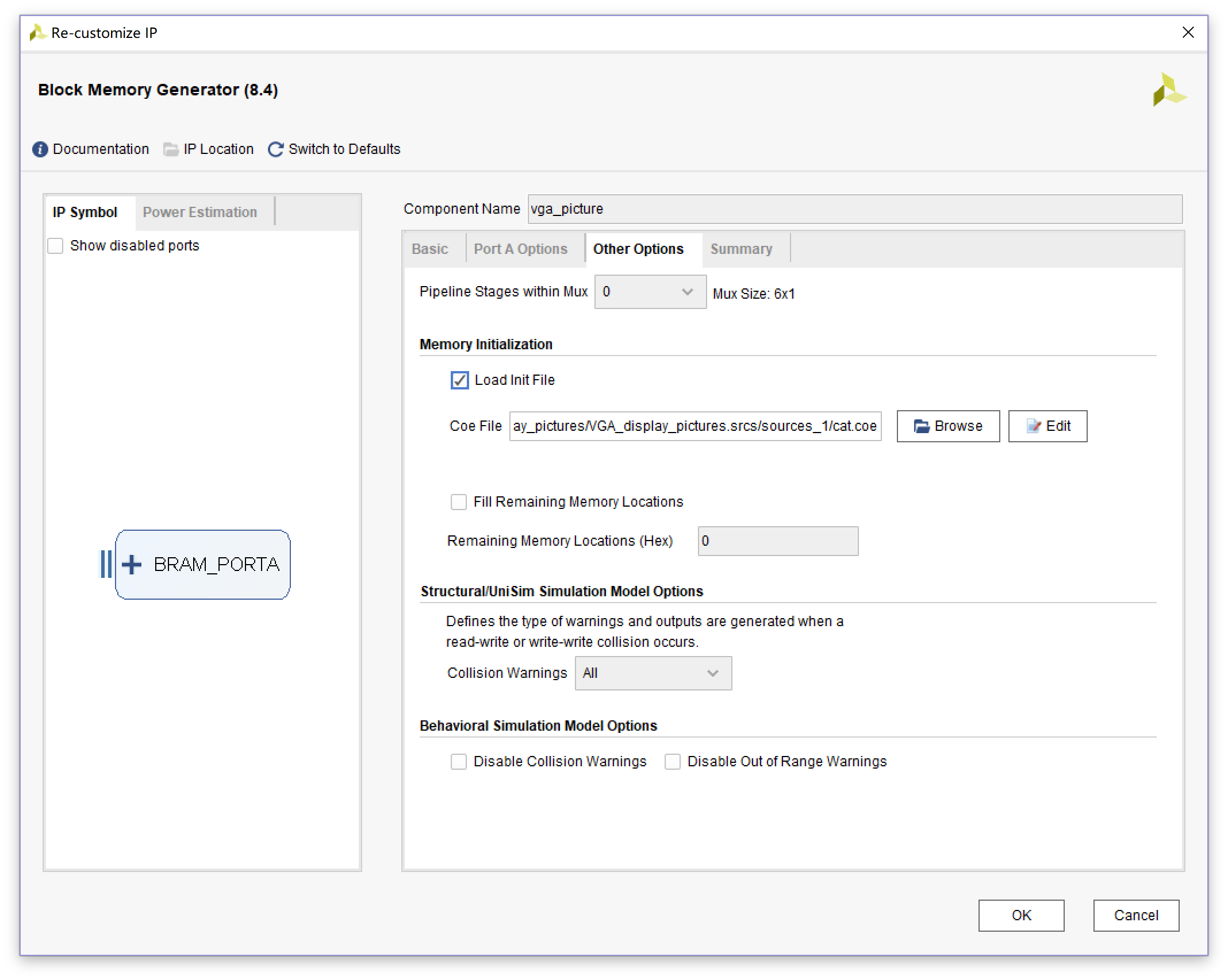
Other Options里,装载 .coe文件。
顶层文件
1
2
3
4
5
6
7
8
9
10
11
12
13
14
15
16
17
18
19
20
21
22
23
24
25
26
27
28
29
30
31
32
33
34
35
36
37
38
39
40
41
42
43
44
45
46
module VGA_display_pictures_top
(
input clk,reset,
output [11:0] rgb_data,
output hsync,vsync
);
//信号声明
wire [14:0] addr;
wire [11:0] rom_data; //rom输出rgb信号
wire [9:0] pixel_x,pixel_y;
wire video_on;
vga_sync U_vga_sync
(
.clk(clk),
.reset(reset),
.hsync(hsync),
.vsync(vsync),
.pixel_x(pixel_x),
.pixel_y(pixel_y),
.video_on(video_on),
.p_tick(p_tick)
);
vga_display U_vga_display
(
.clk(clk),
.reset(reset),
.pixel_x(pixel_x),
.pixel_y(pixel_y),
.rgb_in(rom_data),
.rgb_out(rgb_data),
.addr_out(addr),
.video_on(video_on),
.p_tick(p_tick)
);
vga_picture vga_picture
(
.clka(clk),
.addra(addr),
.douta(rom_data)
);
endmodule
整体连线图

总结
- 为了防止自己忘记,所以写下来;
- 暂时先写这么多,以后再补充。