最近接触了 Verilog-A。记录一下 Cadence AMS-Designer 数模混合的仿真过程。需要用到的软件有 Cadence IC617, INCISIVE152。
INCISIVE152 的安装可以参考 https://blog.csdn.net/yy345730585/article/details/90407408
初始化设置
在打开 cadence 的文件夹下面需要新建一个‘hdl.var’文件,内容如下:
1 | softinclude $INCISIVDIR/tools/inca/files/hdl.var |
其中 $INCISIVDIR 是 Cadence INCISIV 的安装路径。
需要在文件‘cds.lib’中加入一行:
1 | SOFTINCLUDE $INCISIVDIR/tools/inca/files/cds.lib |
Verilog-A 设计 — 以理想 DAC 为例
ieadl_dac (verilogA cellview)
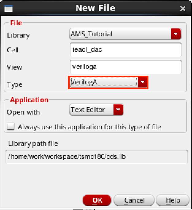
首先创建一个新的 Library 叫做 ‘AMS_Tutorial’。然后创建一个 verilogA cellview 叫做 ‘ieadl_dac’。文件内容如下:
1 | // VerilogA for AMS_Tutorial, ideal_dac, veriloga |
保存后如果没有错误会自动弹出一个创建 symbol 的窗口,确保 symbol 正确创建了。
dac_driver (verilog cellview)

然后创建一个 verilog cellview 叫做 ‘dac_driver’。文件内容如下:
1 | //Verilog HDL for "AMS_Tutorial", "dac_driver" "functional" |
保存后如果没有错误会自动弹出一个创建 symbol 的窗口,确保 symbol 正确创建了。
interconnect elements
由于 dac_driver 是一个 Verilog 的 cellview,其输出是数字量,而 ieadl_dac 是一个 verilogA 的 cellview,其输入是模拟量,因此需要 interconnect elements 来进行数字量和模拟量之间的转换。AMS-Designer 可以自动创建 interconnect elements,不过自己来实现这个连接器,连接器应该有两种形式,分别是数字量到模拟量的转换和模拟量到数字量的转换。
a_d (VerilogAMS cellview)
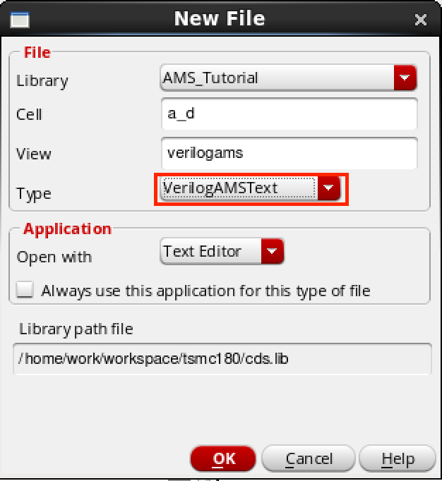
创建一个 VerilogAMS cellview 叫做 ‘a_d’。文件内容如下:
1 | //Verilog-AMS HDL for "AMS_Tutorial", "a_d" "verilogams" |
保存后如果没有错误会自动弹出一个创建 symbol 的窗口,确保 symbol 正确创建了。
d_a (VerilogAMS cellview)
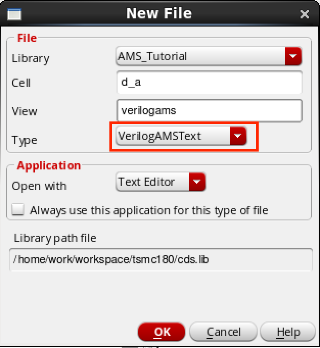
创建一个 VerilogAMS cellview 叫做 ‘d_a’。文件内容如下:
1 | //Verilog-AMS HDL for "AMS_Tutorial", "d_a" "verilogams" |
保存后如果没有错误会自动弹出一个创建 symbol 的窗口,确保 symbol 正确创建了。
ideal_DAC_test (schematic cellview)
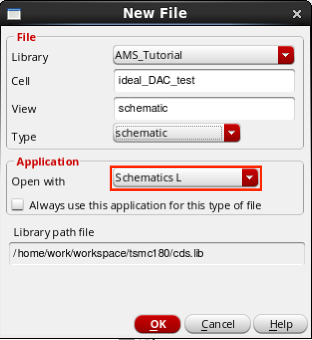
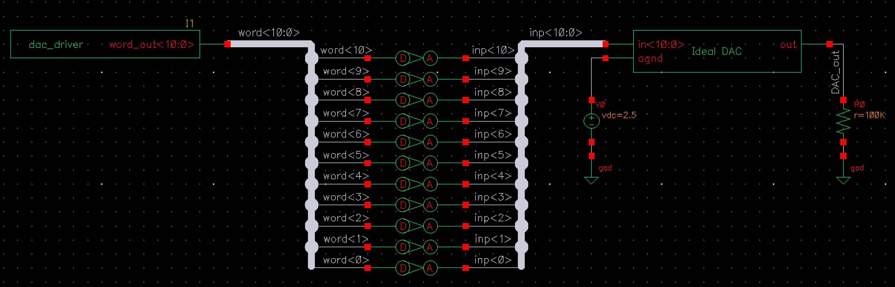
创建一个 schematic cellview 叫做 ‘ideal_DAC_test’。将器件按照下图进行连接。
仿真
config (config cellview)
创建
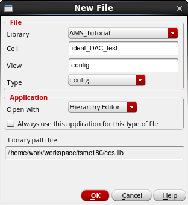
为 ideal_DAC_test 创建一个 config cellview,如下图所示。
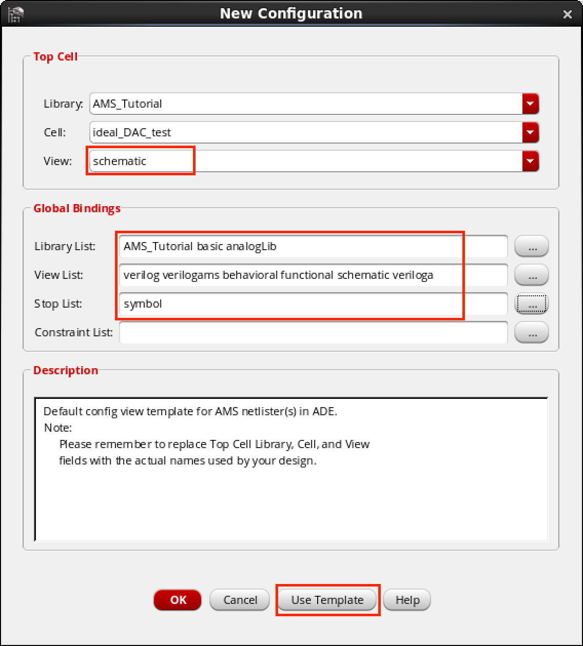
创建完成后,配置窗口会自动弹出,如下图所示,首先选择 ‘Use Template…’,在弹出来的窗口中选择 ‘AMS’。剩下的信息按照下图配置。
创建完成后,把 config(Hierarchy Editor) 和 Schematic 窗口都关闭。
配置 View To Use
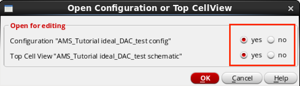
然后再次打开 config 窗口,这时会弹出一个窗口,两项都选 ‘yes’,如下图所示。
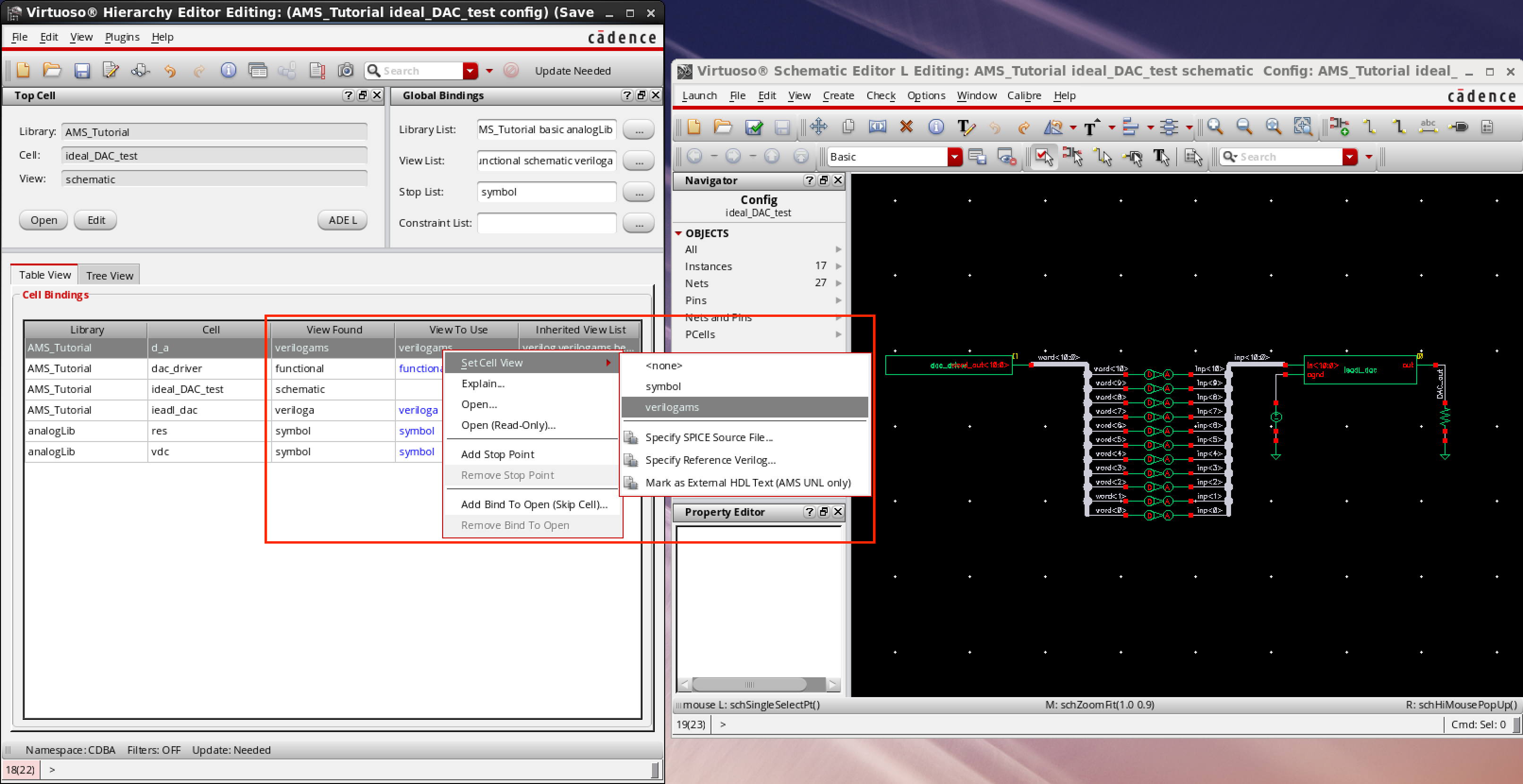
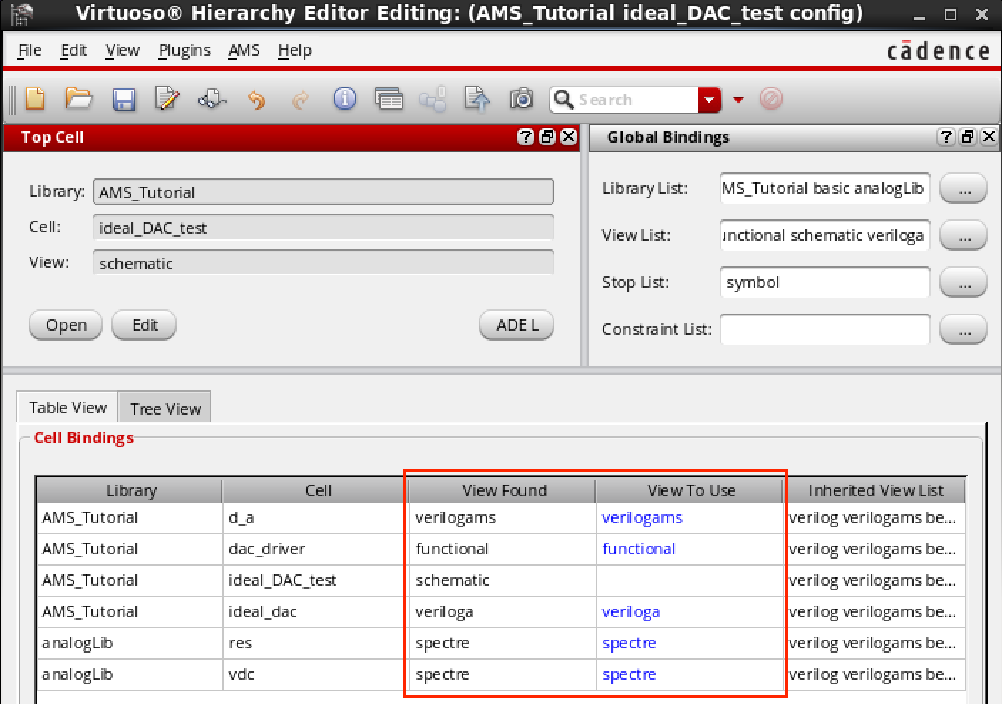
点击 ‘OK’ 之后会看到 config 和 schematic 窗口都一起打开了。在 Hierarchy Editor 窗口中,右击 View To Use 上右击,选择 Select View,配置成如下图所示。
配置 AMS
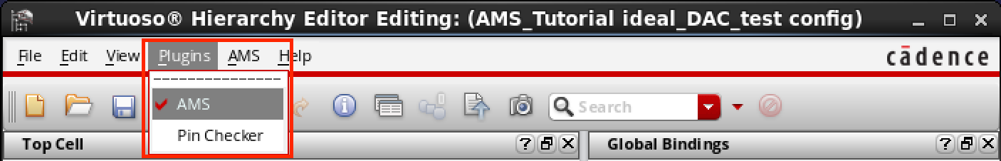
点击 Plugins -> AMS,然后 AMS 选项就会出现在 Hierarchy Editor 窗口中了。
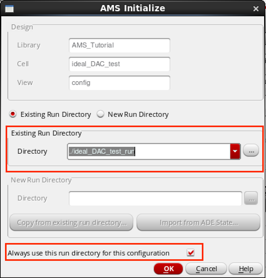
然后点击 AMS -> Initialize,配置 Run Directory,并且在 Always use this run directory … 后面打钩。
在 AMS -> Quick Setup 中,配置 hdl.var 为之前初始化设置中创建的 hdl.var 文件。

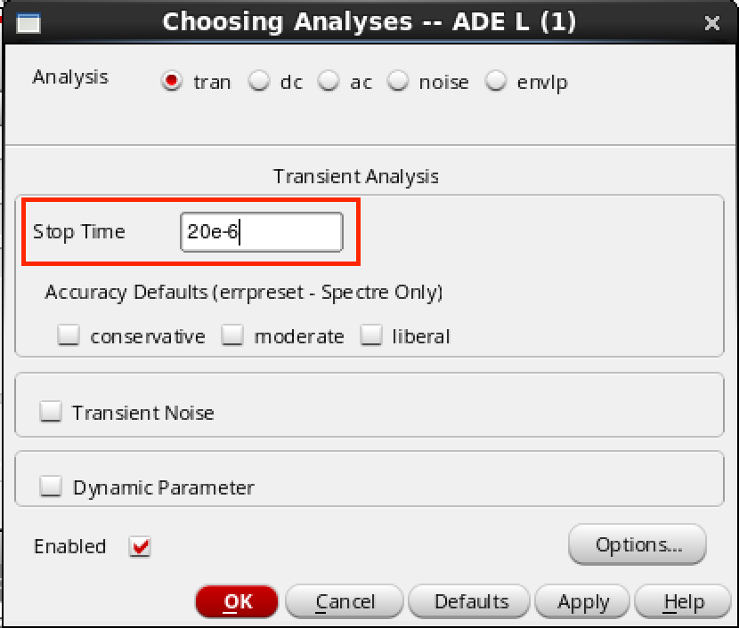
在 AMS -> Detalied Setup -> Analyses 中设置仿真结束时间,这里设置的是 20e-6。
上面几步做完了记得保存一下。
运行仿真
点击 AMS -> NetList and Run,打开一个 config 窗口,这里也可以设置仿真时间。需要注意的是 Save/Plot… 这个选项,该选项可以将需要观察的信号添加进来,不过不建议在这里添加,而是 Netlist 之后再添加,更加方便。
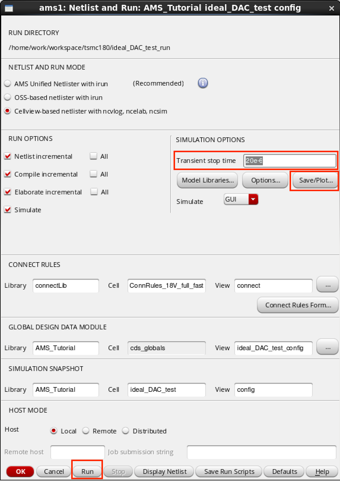
在上面的窗口中点击 Run,如果没有错误会弹出 SimVision 窗口。
在 Design Browser 窗口中想要观察的信号上右击 -> Send to Waveform Window,然后再点击 SimVision Console 窗口中的 Run 按钮,仿真就开始运行了。
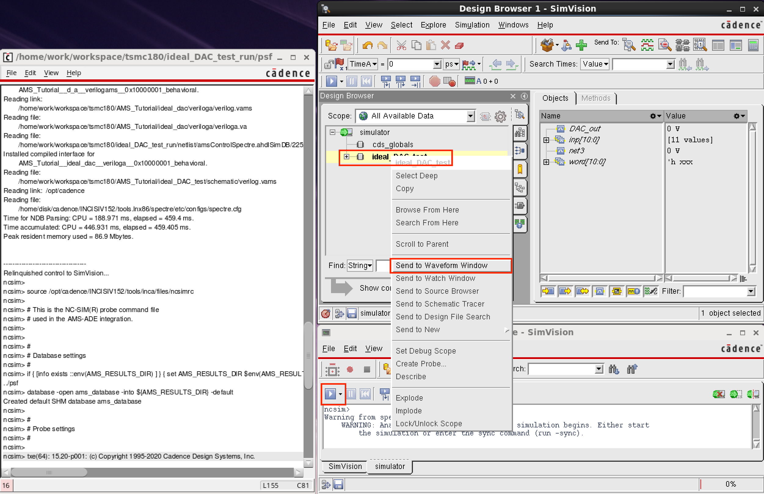
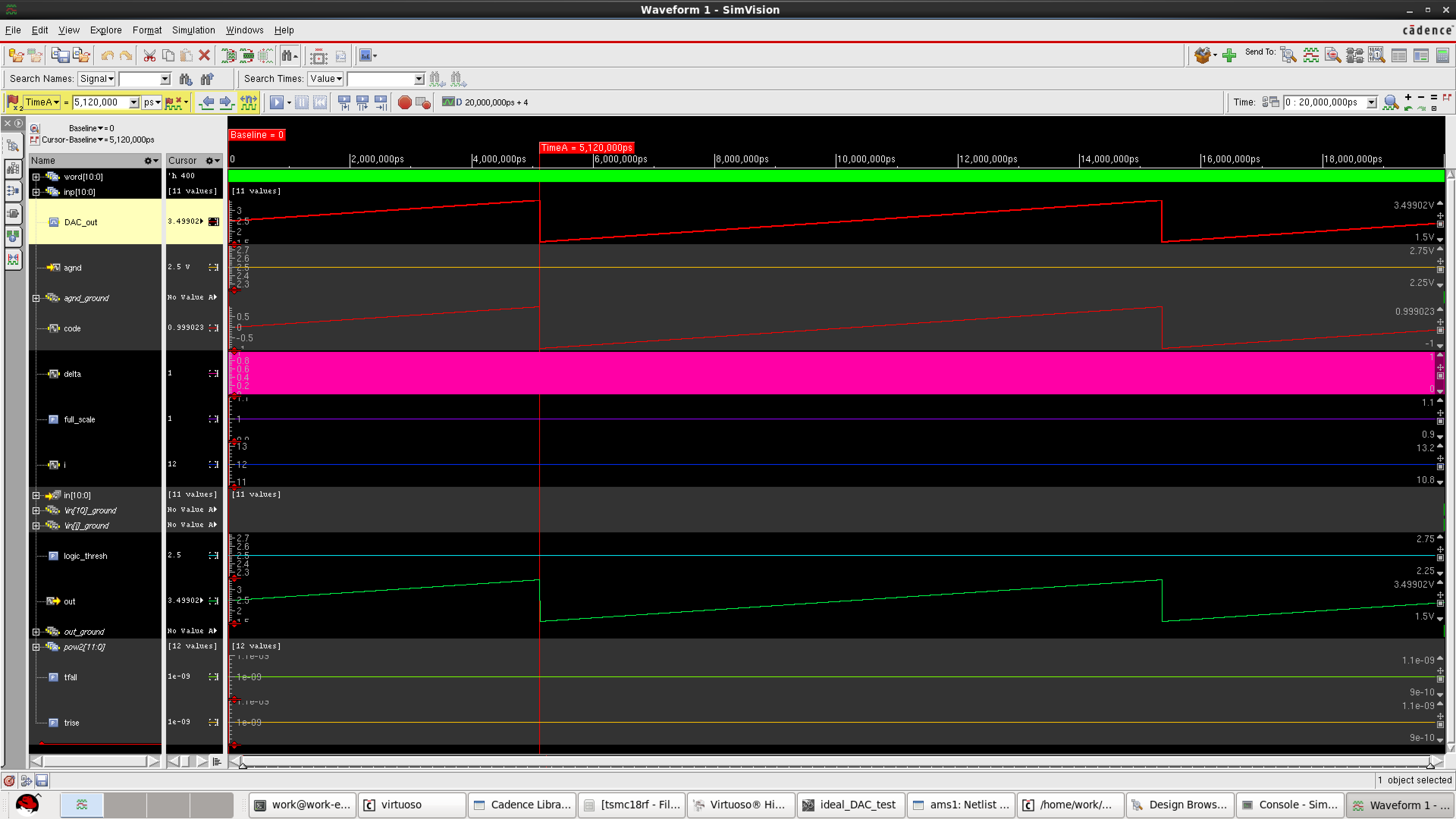
PS:如果模拟量信号观察不到,但可以看到数值,可能需要设置一下 View -> Zoom -> Full Y.
Reference
https://blog.csdn.net/YYP_8020/article/details/107332430
Cadence Verilog-AMS Language Reference
$INSTALL_DIR/doc/verilogamsref/verilogamsref.pdf
Virtuoso AMS Simulator User Guide
$INSTALL_DIR/doc/amssimug/amssimug.pdf
Cadence NC-Verilog Simulator Tutorial with SimVision
$INSTALL_DIR/doc/ncvlogtut/ncvlogtut.pdf
https://designers-guide.org/index.html